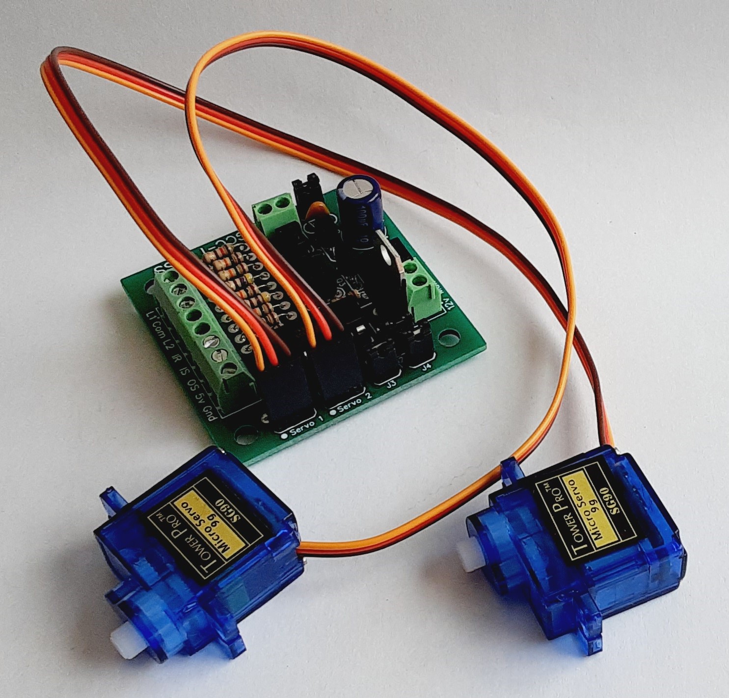
GCC-1 Description
.:
The GCC-1 has been designed to protect railway crossings on your layout. Each crossing can have two
operating LED cross bucks at each crossing location, one for each side of the track.
The controller can also protect multiple tracks at each crossing if so desired. This is done by installing an infrared
receiver and transmitter across all the tracks.
Each set of crossing signals operate just like the prototype. The signals begin to flash when the train first passes
either of the sensors furthest away from the crossing and will extingish after the last car has passed through the crossing.
If the train does not pass through the crossing, the flashers time out and turn off until the train interupts one of the sensors.
If gates are used at your crossings, the LEDs will begin to flash and the gates will then lower about 2 seconds later. Once the train
passes, the gates will rise and then the LEDs will go out a second later.
The gate function can be disabled if desired.
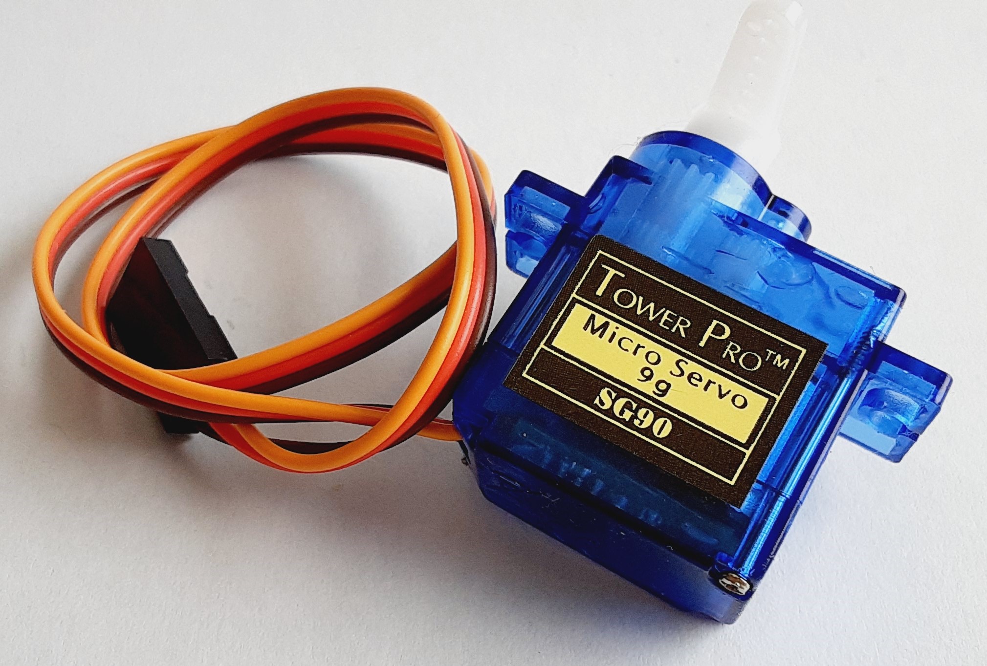
Operates two servo motors for raising and lowering gates at the crossing.
Manual control of each of the crossing signals is also possible with the addition of a switch on your control panel or facia board.
The GCC-1 board has outputs for each crossing that can be used to connect to external devices such as a bell circuit,
automated traffic lights or a simple LED status indicator on a control panel.
This grade crossing controller will operate any type of crossing gate with the following LED configurations:
Common anode (+), Common Cathode (-), or two LEDs wired back to back.

GCC-1 Features
.:
* Drives common anode, common cathode and back to back LED signals.
* Designed to operate automatically, but can be controlled manually.
* Can be used to protect multiple tracks at any crossing.
* Can be triggered from multiple sources, however, infrared LED detectors work best.
* Terminal strip for easy connections.
* Operates two servo motors for gates. (If required)
* External outputs for connection to other devices.
* Low current output for LED signals.
Back to top

GCC-1 Notes
.:
Connections
Connections to the GCC-1 board are shown for several LED output options.
Train Detection Sources
The GCC-1 has been designed to use infrared LEDs and receivers for train detection. There are 4 LEDs and 4 receivers
that need to be placed as indicated in the installation instructions in order for the controller to operate properly.
Although other detection devices can be used, such as block occupancy detectors, they are not recommended unless they
are detecting only small sections of track as shown in the installation instructions.
Manual Switches
The use of a simple switch connected to the GCC-1 board will allow for manual operation.
Back to top

GCC-1 Board Connections
.:
Power
The GCC-1 board operates on 12 volts dc only. The use of any other voltage or supply will damage the circuit.
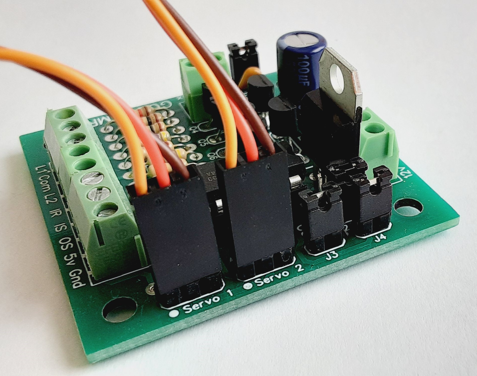
Terminal Connections
L1 - LED 1.
L2 - LED 2.
COM - LED common lead (+ or -).
IR - Sensor infrared LED.
IS - Inner infrared sensor output lead.
OS - Outer infrared sensor output lead.
5V - 5 volt output to infrared sensor.
GND - Ground.
Aux - Switched output for external devices.
Servo1 - Servo motor 1.
Servo2 - Servo motor 2.
Back to top


