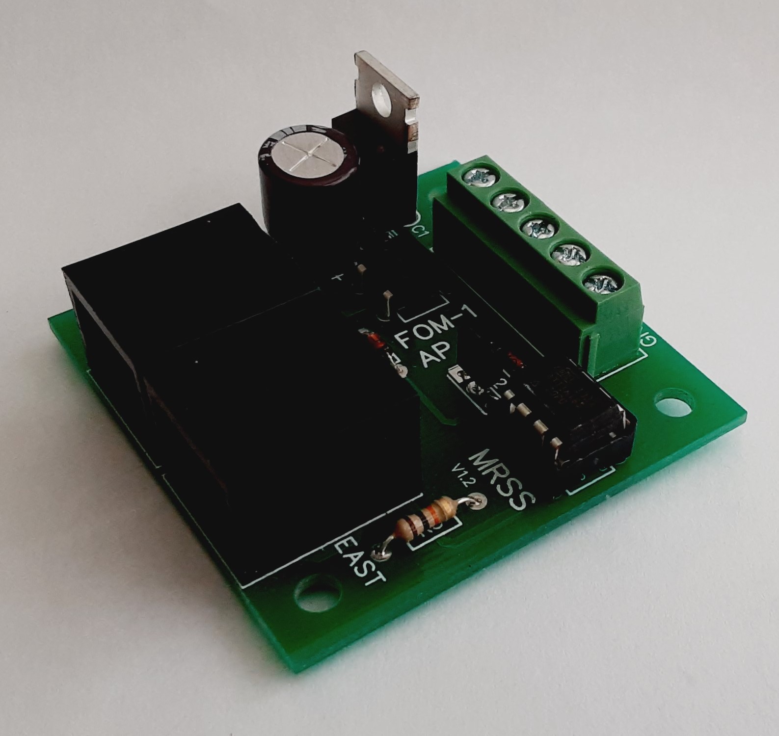

FOM-1 Description
.:
The FOM-1 is similar to the block module with the exception that it uses an external optical sensor to detect train movement.
Although designed for Free-mo modules, the FOM-1 can be used on any model railroad layout where optical detection is required.
The external optical sensor, OPB704WZ, consist of an infrared LED (transmitter) and a photo transistor (receiver). The sensor is placed between isolated sections of track or blocks and is used to detect rolling stock that does not draw current like a locomotive or lighted car. Without the optical sensor, a block signal would display a clear signal as soon as the locomotive or lighted car would clear the block even though other cars may still occupy the block or section of track. This would not be a realistic way to operate signals.
The FOM-1 board consumes very little current. The board can be connected to a 12 volt power supply.
The Optical Detection Module has been designed for universal operation. The occupancy bus is compatible to work with any Free-mo module that follows the Northern California Free-mo wiring standards for the occupancy bus.

FOM-1 Features
.:
* Microprocessor controlled for smooth signal operation.
* Low power consumption. Operates on 12 volts, AC or DC.
* Follows the Northern California Free-mo wiring standards.
* RJ45 jacks provide easy occupancy bus connections.
* Easy to install.
* Terminal strip for easy power and optical sensor connections.

FOM-1 Notes
.:
Connections
Connections to the FOM-1 board are very simple. There are two screws to connect power and three for the optical sensor.
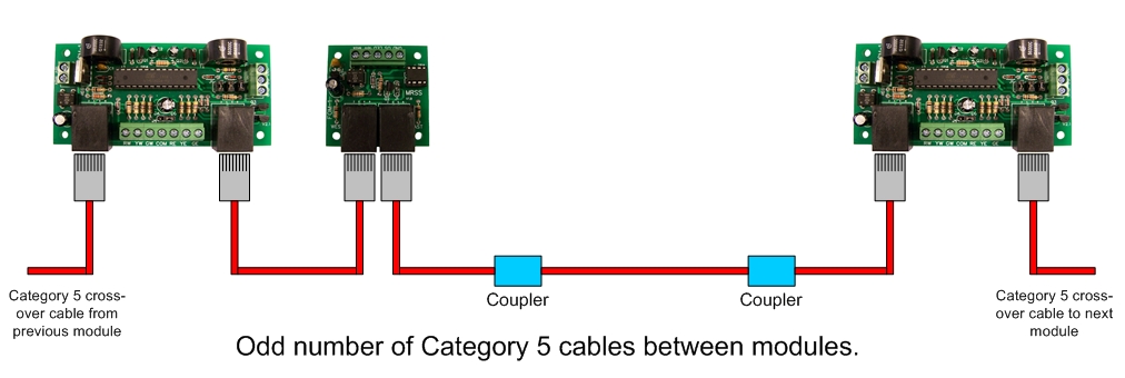
Buss occupancy connections are made by plugging in the category 5 crossover cables from the adjacent modules
The FOM-1 board operates on an AC or DC input voltage of 12 volts.
Terminal Connections
GND - Ground or 0 volt connection.
LED - Power output to the optical sensor LED.
OS - Optical sensor input.
18v Max - Power input.

FOM-1 Power
.:
Power Sources
The FOM-1 can be powered from several sources. The maximum current draw for the unit is about 45mA.
-- A separate AC adapter that can supply between 8 and 18 volts AC or DC.
-- Connecting the board to the accessory bus.
-- Connecting the board to a 12 volt power supply.
-- 12 volt battery.

FOM-1 Optical Sensor
.:
FC-51 Optical Sensor
The original optical sensor used with the FTM-2 was the OPB704WZ. This has now been replaced by the FC-51 sensor due to cost. Both sensors are made up of an infrared LED and a photo transistor. Another option would be to use standard infrared LEDs and photo transistors. Either option will work when both are connected in the same manner.
If using something other than the OPB704WZ or FC-51 sensors, be sure that the receiver is a photo transistor and not a photo cell as they have different characteristics and should not be interchanged.


