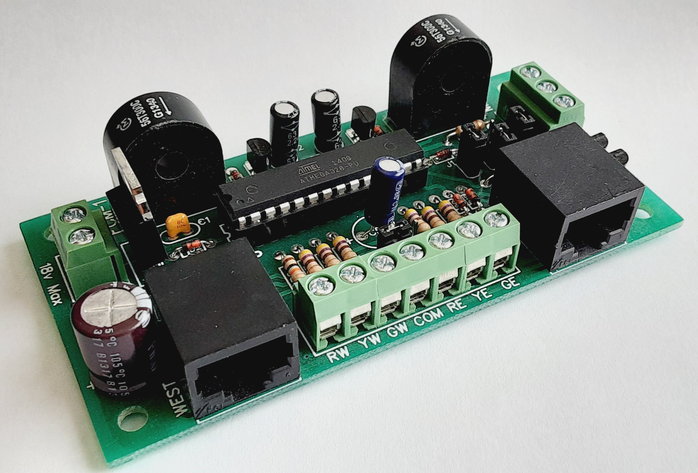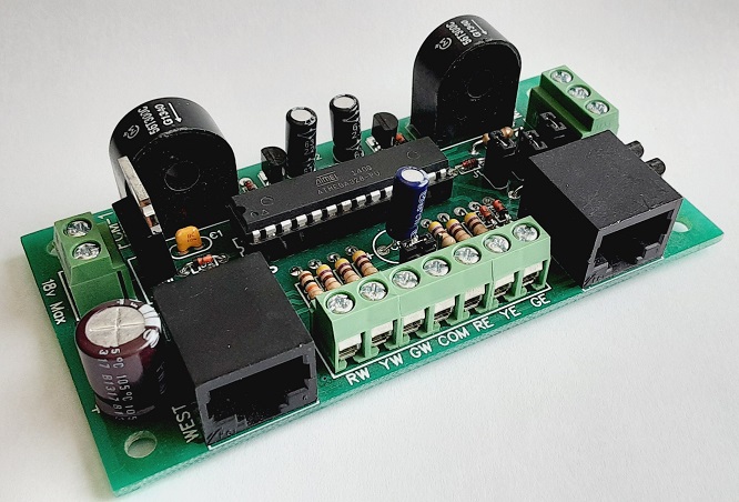

FCM-1 Description
.:
The FCM-1 has been designed to simplify wiring and the need to install additional circuit boards just to get a couple of signals operational. Everything from block detection to signal driver has been designed into this Signal Cascade Module which will allow the user to quickly get a set of signals up and running. The Signal Cascade Module also eliminates the need to have occupancy bus cables which connect to other Free-mo modules remain hard wired during transportation. With the quick connect RJ45 jacks, the occupancy bus cables are easily plugged or unplugged from the Free-mo module during setup and take down.
Although designed for Free-mo modules, the FCM-1 can be used on any model railroad layout where signals is required.
Train detection is accomplished by routing the DCC track feeders through either the east or west air core transformers located on the Signal Cascade Module. When current flows through the track feeder wire, the Cascade Module detects that current and produces a red stop signal for the signal protecting that section of track.
The external optical sensor, OPB704WZ, consist of an infrared LED (transmitter) and a photo transistor (receiver). The sensor is placed between isolated sections of track or blocks and is used to detect rolling stock that does not draw current like a locomotive or lighted car. Without the optical sensor, a block signal would display a clear signal as soon as the locomotive or lighted car would clear the block even though other cars may still occupy the block or section of track. This would not be a realistic way to operate signals.
The FCM-1 board consumes very little current. The board can be connected to either a 12 volt supply or the Accessory bus for power. The type of signals connected to the Cascade Module is limited to LED signals that draw a maximum of 20mA per LED. There is no need to install external current limiting resistors between the FCM-1 and the signals as those resistors are part of the circuit board design.
The Signal Cascade Module has been designed for universal operation. The occupancy bus is compatible to work with any Free-mo module that follows the Northern California Free-mo wiring standards for the occupancy bus.
LUNAR LED OPTION
The FCM-1 board can be ordered with the Lunar Led output option. This feature must be requested when placing your order as it is a customized feature that must be programmed into the FCM-1 board. There is no extra charge for this added feature.

FCM-1 Features
.:
* Operates two, 2 aspect or 3 aspect signal heads.
* Drives both common cathode LED and common anode LED signal heads.
* On board isolated block detection for both east and west direction.
* Optical sensor input for detecting non current demanding rolling stock.
* Can operate independently or with other Free-mo signal boards that follow the Northern California Free-mo wiring standards.
* Can be triggered from multiple sources such as the built in block detectors or external optical sensors.
* Steady or flashing advance approach signal.
* On board current limiting resistors for all LED outputs.
* All inputs have protection from incorrect voltages from adjacent modules.
* Terminal strip for easy connections.
* Power supply input voltage 12 volts, AC or DC.
* Simple connections to other modules with on board RJ45 jacks.
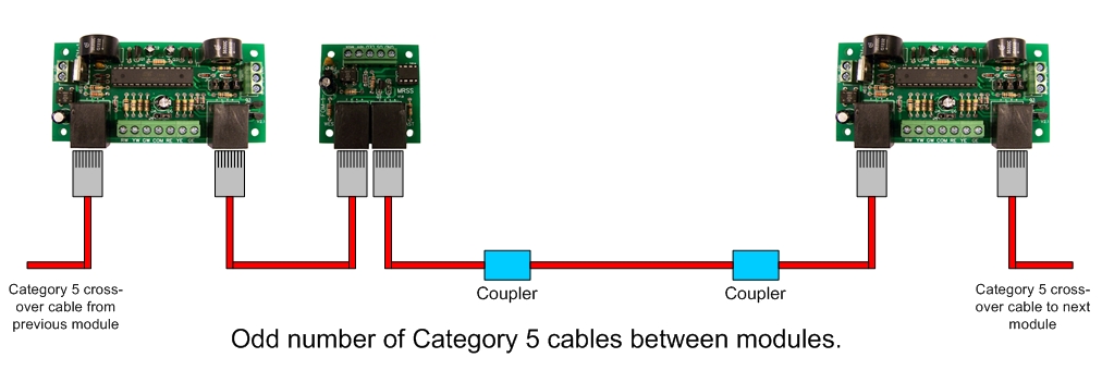
* Requires 2 category 5 cross over cables to connect to other modules.
* Low current output for LED signals.
* LUNAR Led driver option is available with custom programmed versions of this board.

FCM-1 Notes
.:
Connections
Connections to the FCM-1 board are very simple. There are two air core transformers for block detection in which the track feeders pass through between the DCC bus and your tracks. There are two screws to connect power, three for the optical sensor and seven for the signals.
Once the board is mounted under your module and the wires are attached to the terminals, you are pretty much done. The only connections left to be made are by plugging in the category 5 crossover cables (used for the occupancy bus) from the adjacent modules.
The FCM-1 board operates on 12 volts. The use of any higher voltage source will damage the circuitry.
Terminal Connections
GW - Green LED for the west signal.
YW - Yellow LED for the west signal.
RW - Red LED for the west signal.
COM - Common lead for both east and west signals.
GE - Green LED for the east signal.
YE - Yellow LED for the east signal.
RE - Red LED for the east signal.
GND - Ground or 0 volt connection.
LED - Power output to the optical sensor LED.
OS - Optical sensor input.
12v Max - Power input.
J1 - Lunar Led* (Available on custom programmed units)

FCM-1 Power
.:
Power Sources
The FCM-1 can be powered from several sources. The maximum current draw for the unit is about 60mA.
-- A separate AC adapter that can supply 12 volts AC or DC.
-- Connecting the board to the accessory bus.
-- Connecting the board to 12 volt power supply.
-- 12 volt battery.

FCM-1 Optical Sensor
.:
FC-51 Optical Sensor
The original optical sensor used with the FTM-2 was the OPB704WZ. This has now been replaced by the FC-51 sensor due to cost. Both sensors are made up of an infrared LED and a photo transistor. Another option would be to use standard infrared LEDs and photo transistors. Either option will work when both are connected in the same manner.
If using something other than the OPB704WZ or FC-51 sensors, be sure that the receiver is a photo transistor and not a photo cell as they have different characteristics and should not be interchanged.

FCM-1 Signal
.:
LED Signals
The FCM-1 board has been designed to accept most LED signal types. This includes signals that are...
Common cathode, which is a common negative lead.
Common anode, which is a common positive lead.
3 LED signals, having one led for each color displayed, Red, Yellow and Green.
2 LED signals, having a bi-color Red and Green LED that can display all 3 colors.
2 LED signals, having one Red led and one Green LED.
LUNAR signals, having one white led illuminate while the east bound signal displays either approach aspects.
For proper operation, the signal type used must be matched to the chart in the installation instructions and the on board jumpers must be set correctly. There is no need for external current limiting resistors between the signal and the FCM-1 board as the resistors are built onto the FCM-1 board.
Non LED Signals
The FCM-1 has been designed to drive LED signals that require less than 20mA of current directly from the terminal screws on the board. Incandescent bulbs can be used as signals but cannot be connected directly to the FCM-1 board. Doing so will damage the circuitry. A set of transistors or lamp drivers need to be connected to the signal output in order to operate signals that have light bulbs.


